Tuesday, September 29, 2015

ADDING A GSM-4G RADIO TO BRINKS 4000B

When adding a radio on the brinks control panel be sure to check the panel version before adding the GSM-4G. The system will only accept the GSM-4G if the panel has the latest firmware under the 4000B updates.

Once you've determined that the panel is compatible find the best location to install the radio. After you install the radio use the wire harness to power the radio off the secondary power supply from the control panel. You will need to wire the remaining two wires to the bus on the PCB to match the wiring on the radio.

Now that the radio is ready for programming let's get started. First connect your programmer and login to the panel. Next request the panel to learn in new devices. Now that the radio has been found and added let's check the signal strength. Click on the new GSM and continue pressing enter until you see the radio bars. If you have 3 or more your ready to move on.

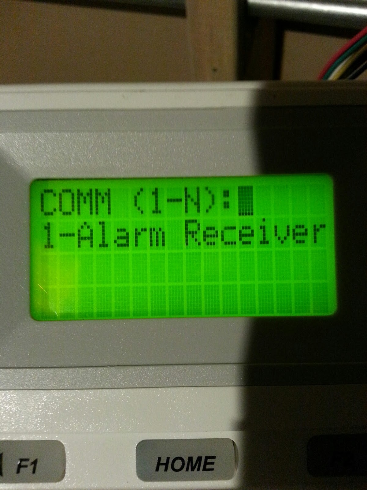
You will need to go to standard programming> account> enter> enter>  when you see account 2 add the same account number and phone number as account 1. Now you will need to back out and go to COMM and create a COMM 2. After pressing 2 under COMM be sure to choose GSM-SIA and move to Back Up and choose yes. Unplug the land line if you have one and send a customer test. Congratulations on installing your first radio on the new Brinks panel.


Wednesday, July 8, 2015

Brinks/Broadview Smoke Detector Installation

Adding or Replacing a Fire Alarm

When adding a smoke detector on a Brinks or Broadview system be sure to wire the high side and low side of a 2112i3 smoke detector in the same order as it was wired in the panel. Also be sure to place the resistor in the field at the EOL for proper reporting. After you've installed the smoke detector connect your programmer and go to standard programming to add the zone. Here you will enable the zone and choose the zone type as fire. After that go to advance programming and choose account, here you will build your timer test. Please make sure you start with account 1 as your timer reporting account.

When replacing a smoke detector with a 2112i3 you should be able to swap without any additional programming. If you are swapping a single smoke detector any 4 wire System Sensor/DSC smoke detector will work as a replacement. If you have multiple smoke detectors on a single zone then you will need to get a similar smoke or replace all smokes. The DSC smoke will not work in line with the BV smoke.


Wednesday, June 24, 2015

Trouble with 6280WADT or 6280SADT?


Custom Touch Screen Keypads For ADT 6280ADT Systems 


6280WADT & 6280SADT Keypad Software Upgrade
The Latest Software Upgrade for the 6280 Keypad is: 4.1.54
Current Upgrade Posted: 05/18/2015
 
 
Instructions: How to Save Software on SD Card and Update Software on 6280 Keypad
Controller
1. Insert a blank SD card into your device drive so you can download the software onto the
SD card

2. Click on the DOWNLOAD button above and click on Save
 
3. Once saved, double click 6280_V04.1.54.exe. Extract files to your desktop, or to a directory
of your choice. Once the files are extracted, copy them to the SD card, or extract all files from
6280_V04.1.54.exe directly to the SD card. ALL THE BELOW FILES MUST APPEAR ON
THE ROOT OF THE SD CARD FOR THE UPDATE TO BE SUCCESSFUL
 
4. Take the SD card with the software downloaded and insert it into the slot on upper right side
 of the 6280 Keypad. You will hear a snap when the SD card is inserted correctly.
 (For help locating the SD card slot refer to the image below).
 
5.Now take a paper clip and push in the reset button located on the lower right side of the
keypad. (The Reset button is directly behind the “Message LED on the right side of the plastic.
(For help locating the Reset button refer to the image below).
Once pressed the 6280 Keypad will update the new software. You will see the system/display
reboot which will take about 1 minute.

A message on the screen will appear stating, “REMOVE THE SD CARD AND PRESS OK
TO RESET KEYPAD”. Press ok and your keypad will reboot. As soon as the display comes up
the software update will be complete.

     
    If you don't have a paper clip you can use the tools icon + advanced + reset keypad.

Tuesday, June 9, 2015

5834-4 HIGH SECURITY MODE KEYFOB


Programming
  • Each 5834-4 transmitter has two unique serial numbers assigned during Loop Numbers for the 5834-4 Buttons manufacture.Each button on the unit also has a distinct "loop" number (refer to the Loop Number at right) that you must program into the control panel during installation.
  • Assign each button to an individual zone and designate the Input Type as "BR" (Button Type).
  • When prompted for the serial number, press and release the appropriate button(s) twice, or, manually enter the serial number at the keypad.
NOTE: Serial #2 is one (1) digit higher than serial #1, which is printed on the rear of the transmitter.
                                                                    Hand Model Cliff S.
USING HIGH SECURITY MODE IN COMPATIBLE RECEIVERS AND LOCALLY IN AN RF KEYPAD (eg., 6150RF) 
If used with LYNXR/Quick Connect Series controls earlier than Revision 13.1, Standard Mode must be selected. First select High Security mode, then activate it. Activation syncs the key fob with the security system.
  • 1. Select High Security mode: Mode Simultaneously hold down for 5 secs… A - C - D (LED flashes Red when transmitting) High-Security B - C - D (LED flashes Green when transmitting) Standard
  • 2. Activate High Security mode: • if the key fob is enrolled into the panel, put the security system into Go/No Go Mode 
  • 3. If the key fob is enrolled locally into a 6150RF, go to Step 3 of 6150RF “Programming WITH Local Wireless Keys”, then press the appropriate set of buttons as follows: Serial Number Simultaneously hold down until beeps sound… A - B - C buttons (system beeps twice to confirm) 1 A - B - D buttons (system beeps twice to confirm)
  •  
    Please see below for instructions provided by our small business team.
    ENTER INSTALLER CODE #8 THEN HOLD ALL THREE BUTTONS (NOT PANIC) AT ONCE AND YOU WILL GET TWO BEEPS. THIS CONCLUDES THE PROGRAMMING

Friday, June 5, 2015

Cheat Sheet For GE Concord Panels


Concord 4 – 4321 (Default)
System Programming: [ 8 ] + [ INSTALLER CODE ] + [ 0 ] [ 0 ]
Select "System Programming"
Security--Global Menu--Downloader Code
Security--Global Menu--Installer Code
Security--Partition1--Account # (repeat/copy for mult partitions)
Security--Partition1--Duress Code (9999)

Phones--CS Phone 1—XXX-XXX-XXXX (repeat/copy for multi partitions)

Phone Options--Global--Auto Phone Test--ON

Timers--Global--Next Phone Test--7
Timers--Global--Phone Test Freq—7 (Weekly)

Reporting--Global--AC Failure--ON
Reporting--Partition1--Duress Option--ON

Sensors--Learn Sensors
Sensors--Sensor Text
Sensors--Delete Sensors (Delete any hardware zones not being used)

To Exit, Select "Exit System Programming"

User Programming: [ 9 ] + [ MASTER USER CODE ]
Set Time/Date
Set Master Code
Set any User Codes

CONCORD System Tests:
COMMUNICATIONS TEST: [ 8 ] + [ MASTER USER CODE ] + [ 2 ]
When the panel completes the test, the system returns to the previous arming level
automatically. If the display continues to show PHONE TEST for 1½ minutes or more, enter [ 1 ] + [ MASTER USER CODE ] and recheck phone connection.

15 min SENSOR TEST: [ 8 ] + [ INSTALLER CODE ] + [ 3 ]
Trip each zone/sensor one at a time. Touchpads (and interior sirens) should sound one short,
high-pitched beep and the display should show the sensor name (or number) and OK.
Press the STATUS button when you think all zones/sensors are tested. The touchpad displays
any untested sensors/zones and touchpad panics. If all sensors/zones and touchpad panics
have been tested, the display shows SENSOR TEST OK.
Exit sensor test [ 1 ] + [INSTALLER CODE ]

REPEAT TESTS FOR MULT PARTITIONS
Turn Partition Security OFF in SECURITY GLOBAL menu, then use 7+4+2 to change partition without using code.
**

Thursday, May 28, 2015

How to tie a proffessional home automation system to a SW3000?

Years ago you would only be able to tie the Honeywell Vista 128 series panel to a third party automation system, but times have changed!! The 4232CBM or HSPIM as we like to call it, allows you to communicate with the new Pulse ready systems. This module will give you access to the panel through the home remote stations allowing status updates, arming, and disarming. You may provide the 9 pin connector for the contractor but do not connect it due to the liability.

When programming the communication device follow the Pulse programming for installation requirements.

Please see devices


Wednesday, May 20, 2015

Pulse Camera Connection

Using Encoders to connect to the analog camera makes it viewable on your ADT Pulse. The NV412A encoder needs to be connected via Ethernet to the ADT Gateway. Since the Gateway only has one device port, you will need to add the ADT Pulse net gear switch for multiple cameras.

There are two scenarios that you would want to use this NV412A. The first is if the customer has an existing Analog camera system already installed and just want to be able to view 1-10 of the existing cameras on the Pulse. This is easy because all you need is the NV412A. One for each camera. The cameras are already installed, wired, and powered. So just install the NV412A.

The second scenario includes adding a DVR. This would require installing the NV412A before the DVR for recording continually instead of clips. Unplug the BNC cable from the DVR and plug it into the NV412A and then plug a new BNC cable from the NV412A output to the DVR input.

See the illustration below for more information on installing Encoders.


Tuesday, May 5, 2015

A910 Trouble? Who doesn't love tips?


Function
Instruction
Description:
Hard Wired System - Optional Wireless Pendant
This Control is down loadable.
Code

Code

Code

Press 4 hold for three seconds, Code, Code

First two digits of the code
Note: Quick arming is optional in programming
#, Single digit zone number(1-6), Code
Note: The zone light that is bypassed will start blinking

#, 9 or Arm and Disarm system
Press 6 hold for three seconds
Note: After the initial key is pressed the keypad will emit three beeps to indicate the chime is on or two beeps to indicate the chime is off
Place system on test
Press 9 for 3 beeps, enter five digit service code, (will disconnect line and send in Service On Prem)(call back if on same line) then enter 1,7,7,#,1,*,*(might disconnect) if so call back and enter *, 9, 9, * to to go "Off Prem". New code should be 1234.


Press 9 hold for three seconds, Master Code, Single digit user (2-6), #, New Code
Note: A long beep will be heard
Press 9 hold for three seconds, Master Code, Single digit user (2-6), #, 0, 0, 0, 0
Note: A long beep will be heard
OR
Press [9] hold for three seconds, [mater code], [1], [0], [#], code(1-6).
Press 9 hold for three seconds, Master Code, 1, #, New Code
Note: A long beep will be heard
Press 9 hold for three seconds, Master Code, 6, #, New Code
Note: A long beep will be heard. Continue with the rest of the process
Press 9 hold for three seconds, Master Code, 7, #, Enter number of uses (1-254), *, *, A long beep will be heard
Codes are four digits in length
Master Code = User 1
User Codes = User 2-4
Duress Code/User Code = User 5
Temporary Code = User 6

Master Code - Arm/Disarm/Bypass/Add Codes/Change Codes/Delete Codes

User Codes - Arm/Disarm/Bypass

Duress Code/User Code - Duress Code - Arm/Disarm/Transmits a duress alarm

Temporary Code/User Code - Arm/Disarm the number of preset times entered under the number of uses when the code was added

Press 9 hold for three seconds, Master Code, 8, #, 0, *
Note: This will transmit the signal immediately

Hold [9] for 3 seconds (3 beeps), enter [Master code] [8] [#] [0-24] [*] sets time to next timer test from 0-24 hrs.

Press 9 hold for three seconds, Master Code, 8, #, Number of hours (1-24), *
Code


Press and hold the Fire button down for three seconds

Press and hold the Police button down for three seconds

Press and hold the Medical button down for three seconds
* Press 9 (Hold for 3 beeps, enter 5 digit service code,(might be cut off as system sends in "On Prem" signal) enter 1,9,7,#,1,*,* (Might be cut off again) Wait 3 seconds then enter *,9,9,* (Off Prem)
* Must place system on test.

*, 9, 9, *
Note: After one hour the times out. The system's buffer will not retain the "SVC OFF PREM" signal past one hour from the time it was originally generated.
Hold [9] for 3 seconds, enter [master code], [8], [#],0, [*]
View/Clear Memory: Hold [3] for 3 seconds. Last zone tripped will show for 8 seconds. [*] to clear memory.
Press 7 hold for three seconds, Code
Note: The back up battery has to be fully recharged before it will reset. If the back up battery has not fully recharged wait a few hours and perform the procedure again.
Press *
·  Bottom to Top: Power Trouble (Transformer is partially unplugged or breaker is off)
·  Top to Bottom: Defective Control Panel
*


Code

*

*

Press & hold the number 7 key for 3 seconds, then User Code. If not, try *,7, 4 digit user code


Code


*


The keypad and control unit are separate.
If trouble light is lit press 2 hold for three seconds to enter diagnostic mode. Zone(s) that lights up will define problem. See chart below:
Zone 1 - AC Power Failure
Zone 2 - Low Battery / Blown Fuse
Zone 3 - Supervisory / Trouble
Zone 4 - Fail to Communicate
Zone 5 - Memory Error
Zone 6 - Missing Keypad(to clear - Hold number 8 for 3 seconds (beeps)then press *)

Trouble?Alarm Lights Flashing Alternately: Enter # + 0 to clear.

Zone Lights Scrolling Top to Bottom = Defective Control
Bottom to Top = Power Out (Transformer partially unplugged, outlet bad, circuit breaker off or GFI tripped) or a wiring problem within the control.
Press 8 hold for three seconds, Activate Sensors
Note: This is a local test no signal will be transmitted to the monitoring station.

*
Utility Output Command: Hold [0] for 3 seconds, enter [User code] Can be programmed by installer to operate mag locks, electric lights, camera's etc. User code must have a configuration digit of 2, 3, 5, or 7 (programmed by installer)

Thursday, April 30, 2015

Are you aware of zone doubling?

VISTA 21iP vs VISTA 20P


Both the VISTA 21iP and the VISTA 20P (ADT SW3000) support up to 48 total zones. Both systems have 8 hardwired zones built unto the CPU. Both are capable of zone doubling in order to use more than the standard 8 zones without needing a zone expander. The zone doubling allows you to turn the panel 8 hardwired zones into 15.
 
The systems are different when it comes to IP communications for monitoring over the Internet. Whereas the VISTA 21iP has a built-in IP communicator the Vista 20P does not. The Vista 20P is capable of communicating over the Internet but you would need to add a 7847i Internet communicator.


Wednesday, April 29, 2015

How to Replace a Radio on the Brinks Control Panel

When replacing a radio on the brinks control panel be sure to uninstall the current radio and install the replacement radio prior to programming. Once you've replaced the old GSM radio, your ready to begin. First plug in your programmer to the PC board and enter the installer code. Next scroll down to the advance menu and then press enter. Now select device menu.  After you've selected device menu you will need to select the GSM gateway and then replace device. The system will now start the process of replacing the radio. One keynote, If your system is capable of sending an upload do this before replacing the radio to store the current information.

Sunday, April 26, 2015

Are you Brivo Ready?

When servicing an access control system be sure to ask if the fire alarm is associated with the access system. Always document those that you spoke with during the service and the detail of the service performed. Remember egress and access can be affected by the access control systems. Please see information below for more about access control.

Access control systems secure doors using electric locks and restrict passage through those doors to authorized individuals. In the event of a fire, such a system could potentially limit an individuals ability to safely exit and could also restrict access by fire fighters. For this reason, most municipalities have design rules for access control systems and require a permit for their installation and use. 

In general, if a building (or suite within a building) has a fire alarm and an access control system, the systems should be integrated so that if the fire alarm is triggered, the access control system will release it's locks to allow free entry and exit.

 Various factors are considered by a municipality in determining whether such an integration is required, including the type of locks used, which doors are secured, if there are alternative doors that would allow egress, and the floor within a building where the tenant is located.


Saturday, April 25, 2015

How to replace a Pulse gateway

When replacing the gateway on a Pulse system be sure to put the system in install mode. After you've placed the system in install mode go to our Pulse site and select replace existing system. Next you should be asked to enter the old activation key and then the new activation key. Before you move to the next screen replace the old gateway with the new gateway. Now your ready to move on. The system will go through a series of steps and before fully activating the gateway you will be asked to update the system if necessary. Now if you have lights, cameras, locks, or any other appliance on the system don't expect them to work immediately. If you can only control the security system after about 10 minutes then you may want to remove the appliances and reinstall them.


Thursday, April 23, 2015

The Purpose of the Resistor

This is probably the most basic component of all existing electronic components and as the name already implies the main characteristic of this component is resistance. It restricts current flow, higher resistivity value means lower current flow through the resistor and bigger voltage drop across the resistor. When this is placed inside the control panel instead of at the end of the line (EOL) it has been installed incorrectly. This component helps create integrity on the line in the case that there is a fault.

When reading the resistors value while the resistor is part of the electrical circuit, the Digital Multi Meter may not be possible. The reading won't be accurate because other components may be affecting the results. If you need to know the value of resistance for a replacement component please see chart below.

Wednesday, April 22, 2015

Problems with 3PS?

The 3PS issue has been solved :-)!!!! The first thing you need to do is reset your browser by closing the 3PS window and clearing the browsing history. To do this click on the setting wheel in the right corner and select internet options. Then choose delete browsing history. Next select temporary files and cookies, and then click ok. After the browser history has been deleted, try to sign back into 3PS. If you're still having problems contact the help desk.

Ionization vs Photoelectric Smoke Detectors

The fire department favors photoelectric smoke detectors but recommends both. Most builder grade smoke alarms are Ionization smoke alarms but we typically install photoelectric fire detectors. The photo detector will avoid more of the nuisance alarms and notify the occupants when smoke enters the chamber. Most fire deaths are not caused by burns, but by smoke inhalation. Often smoke incapacitates so quickly that people are overcome and can’t make it to an otherwise accessible exit. See below for the difference on how each device works and why you should never tell your customer that the only fire protection they need is the fire protection we offer. The local alarms are great for added protection!

Ionization smoke alarms are generally more responsive to flaming fires.
How they work: Ionization-type smoke alarms have a small amount of radioactive material between two electrically charged plates, which ionizes the air and causes current to flow between the plates. When smoke enters the chamber, it disrupts the flow of ions, thus reducing the flow of current and activating the alarm. 


Photoelectric smoke alarms are generally more responsive to fires that begin with a long period of smoldering (called “smoldering fires”). How they work: Photoelectric-type alarms aim a light source into a sensing chamber at an angle away from the sensor. Smoke enters the chamber, reflecting light onto the light sensor; triggering the alarm


Tuesday, April 21, 2015

The New 5853 Glass Break Dectector

Have you installed or had to service a 5853 glass break detector? If you've installed it without adjusting it for the ambience of the protected area then you're setting up a nuisance alarm. When installing a glass break be sure to adjust the sensitivity for the area it's protecting. If your covering a home theater you might not want to set it too high. If your protecting a bedroom you may want it higher than the theater. You can also determine your settings based on the square footage of the space. However you decide, start with the manufacture instructions for the best results.

Monday, April 20, 2015

Are you qualified to work on that commercial fire alarm?


Service personnel shall be qualified and experienced in the inspection, testing, and maintenance of systems addressed within the scope of this Code. Qualified personnel shall include, but not be limited to, one or more of the following:
  1. (1)  Personnel who are factory trained and certified for the specific type and brand of system being serviced
  2. (2)  Personnel who are certified by a nationally recognized certification organization acceptable to the authority having jurisdiction
  3. (3)  Personnel who are factory trained and certified for fire alarm system design and emergency communications system design of the specific type and brand of system and who are acceptable to the authority having jurisdiction

    If you don't meet any of the qualifications and the equipment fails during a fire alarm after you serviced it, did you know that you can be arrested? Remember this type of alarm is to protect the public and is considered life and property safety equipment. When replacing, altering, or reprogramming this type of equipment you must follow the code for approval.